
Part 1: The Basic Approach
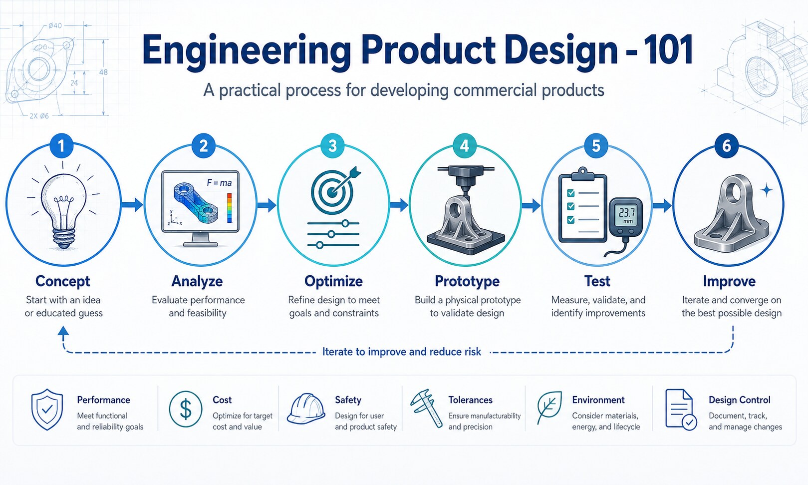
I am not going to tell you that engineering is not difficult. Well trained engineers have a strong foundation in mathematics and science. Upon this they learn specialized skills that enable them to solve complex engineering problems. However, beyond all the math, the overall approach used to design commercial products is fairly simple.
Product design often begins with a guess: "This size seems about right." The next step is to evaluate that guess. Is the component underdesigned, overdesigned, or about right? The initial estimate may be close, or it may be far from the best solution.
In general, engineers seek to minimize, maximize, or optimize a design characteristic. Most often, the goal is optimization because a single characteristic may affect several performance objectives. Consider the simple example of designing a tent pole. Our initial concept is a hollow cylinder because hollow cylinders resist bending more effectively than solid cylinders with the same cross-sectional area due to their higher area moment of inertia. As a starting point, we might estimate that a pole with a 1-inch outside diameter and a 3/16-inch wall thickness seems appropriate.
If we stopped there, however, we would not have applied much engineering. We must now consider the performance requirements that the pole must meet. Its axial strength must be sufficient to prevent crushing during use. It must also resist buckling, which is a common concern for long, slender structural members. At the same time, the pole cannot be unnecessarily expensive because every component contributes to the product's overall cost.
In this example, we want to maximize axial strength, maximize resistance to buckling, and minimize cost. The two primary variables are the outside diameter and wall thickness. Increasing either dimension generally improves strength and buckling resistance, but it also increases cost. The objective is therefore to identify an optimal combination of dimensions that balances all three criteria. The pole should be neither too large nor too small.
We begin with the axial stress calculation:
σ = F / A
where F is the axial force applied to the pole and A is its cross-sectional area. To prevent crushing, the stress must remain below the strength of the material. From the equation, we can see that the cross-sectional area may be increased by increasing either the pole diameter or the wall thickness.
Next, we consider buckling resistance. For a slender pole with pinned connections at both ends, the critical buckling load may be estimated using the Euler buckling equation:
Pcr = π²EI / L²
I = π(Do⁴ − Di⁴) / 64
where Pcr is the critical load at which buckling occurs, E is Young's modulus of the pole material, I is the area moment of inertia, L is the unsupported pole length, and Do and Di are the outside and inside diameters, respectively.
The equations show that increasing the diameter has a particularly large effect on buckling resistance because the outside and inside diameters are raised to the fourth power. However, if we entered this problem into an optimization program without practical constraints, it might recommend the maximum allowable diameter, perhaps 10 inches, with an extremely thin wall, such as 1/64 inch. The result would resemble a giant aluminum can.
Although this solution may be mathematically valid, the optimization does not account for every practical concern. A very thin wall could dent easily, potentially causing the pole to collapse under load. A pole with a 10-inch diameter would also be difficult to transport. We therefore need to constrain the optimization to a practical range near the initial estimate, perhaps from 0.5 to 2.0 inches in diameter. Once the required load is known, we can calculate the necessary wall thickness for each diameter within this range.
The next question is whether the pole should be custom made or purchased as an off-the-shelf component. People who are new to engineering design sometimes assume that creating a custom component will save money because an available part appears expensive: "I can make it cheaper." In practice, the opposite is often true. At low production volumes, custom parts may cost 10 to 100 times more to manufacture than standard components cost to purchase.
Returning to the tent pole example, once we know the approximate dimensions, we should investigate which standard sizes are available. We will assume that the pole is made from aluminum, although this material selection would actually need to be made earlier to compare the calculated stresses with the material strength. Using a standard size helps avoid the cost of a custom component and may also eliminate impractical options, such as the extremely thin wall identified by the unconstrained optimization.
After identifying diameter and wall thickness combinations that meet the structural requirements, we can compare their costs. Larger dimensions increase the factor of safety:
FS = strength / stress
However, larger dimensions also increase material use, weight, and cost. Engineering judgment is required to select a reasonable factor of safety. For this example, we might assume that the loads are primarily static and reasonably well known, allowing us to use a factor of safety of FS = 4.
Calculations should be performed for each pole size under consideration. The final selection should be large enough to meet the structural requirements and achieve the desired factor of safety while minimizing cost.
For a product containing multiple poles, the same process should be applied to every component. Changes to the dimensions of one part may also require changes to the couplings and other mating components. Through an iterative design process, the overall product gradually approaches an optimal design.
Much of this work can be completed using CAD and mathematical models before the first physical prototype is built. Ideally, prototypes are used to verify calculations and evaluate aspects of the design that cannot be fully represented in a model. They should not simply be used to test a series of guesses. Trial and error prototyping can be expensive and time consuming, and it is unlikely to produce an optimal design unless the designer happens to get lucky.
This example considers only a simple pole. More complex products have many additional design criteria that must be satisfied simultaneously. Even the pole may require consideration of corrosion resistance, fit tolerances, length tolerances, and paint thickness. Paint thickness is itself an optimized characteristic. If the coating is too thick, mating parts may not fit together properly, and the added material increases cost. If it is too thin, it may not adequately cover the surface, may scratch easily, or may not provide the desired fit between the pole and its coupling.
Part 2: Efficient Engineering Development
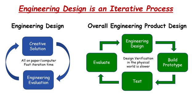
In Part 1, the general approach to commercial product design was presented. Now let's consider how to carry out that process efficiently. Optimizing a design on a computer is much faster and less expensive than relying on trial and error with physical prototypes. The ideal approach is to design the product, optimize it, and then build it.
In practice, however, engineering is an iterative process. As changes are made to optimize one component or feature, other parts of the design often need to be modified as well. Most of these iterations can be completed using CAD and mathematical models (blue cycle below). However, computer models are only representations of the real product. Physical prototypes are still needed to evaluate characteristics that may not be apparent in the models. Prototypes are built and tested, and the results are used to further optimize the design, correct design errors, and identify inaccurate assumptions (green cycle below).
Experienced engineers are better able to judge when a physical prototype is needed and when continued modeling is the more efficient approach. The overall objective is to maximize product performance while minimizing development time, project risk, and overall product cost. Overall product cost includes both the cost of developing the product and the cost of manufacturing each unit.
Part 3: Environmental Conditions
Engineered commercial products are often designed to function across a wide range of environmental conditions. Even if a product performs well in the laboratory, its performance may deteriorate or it may become inoperable when the temperature changes.
High and low temperatures cause materials to expand and contract, which can affect the tolerances between mating parts. These dimensional changes can be estimated by considering the coefficient of thermal expansion of each material used in the design.
Like the optimization problem described in Part 1, the operating temperature range creates two performance requirements that must be met by a single design. The product must function at both low and high temperatures. Although this may seem complex, the same methodical engineering approach can be used to address both conditions.
Other environmental effects can be evaluated in a similar way. These may include embrittlement and fracture at low temperatures, softening and deformation at high temperatures, and water absorption and swelling. Each condition should be considered during the design process to ensure that the product continues to function as intended.
Part 4: Interchangeable Parts
Most people take for granted that if a component breaks, it can be replaced with another component. However, this was not always the case. Centuries ago, many components were custom-made, and the fits between parts were adjusted manually. Today, engineers use tolerances to control component dimensions and make interchangeable parts possible. This is essential in medium-to-high-volume manufacturing because it would be extremely inefficient to custom-fit every part in an assembly.
So, how does an engineer determine which tolerance to use? At first, it may seem logical to make tolerances very tight so that mating parts always fit together properly. However, from a manufacturing perspective, tight tolerances can be difficult and expensive to maintain. They may also result in low manufacturing yields and higher component costs. Looser tolerances are easier and less expensive to produce, but they may prevent the product from meeting the design requirements described in Part 1.
To address this challenge, engineers often select a manufacturing process that naturally produces tolerances suitable for the design. Standard tolerances can then be used for most dimensions, while tighter tolerances are applied only to critical features and fits. Standard tolerance ranges may be found in published references or provided by the manufacturer.
Tolerances define the acceptable range of values that a component dimension may have while still remaining within specification. In relation to the calculations discussed in Part 1, tolerances represent variation from the nominal dimensions. This variability must be considered during the design process so that the product continues to function properly even when individual parts are manufactured near the limits of their allowable ranges.
Part 5: Design Control
In the previous section, we discussed interchangeable parts. Although interchangeability is often a desirable goal, it may not always be possible because products and their components evolve over time. When older components can still be used in newer designs, this is referred to as backward compatibility. Backward compatibility may be maintained at the module level even when individual components within the module are no longer interchangeable.
For example, suppose the manufacturer that supplies a particular pin goes out of business. A suitable replacement pin is identified, but its diameter is slightly larger. The mating hole must therefore be changed to accommodate the new pin. As a result, the old and new pins are no longer interchangeable. However, the module containing the pin and mating hole may still remain interchangeable with higher-level components in the overall assembly.
Design control is required to manage this type of change properly. The revision of the pin might be increased from Revision A to Revision B, while the revision of the housing containing the mating hole might increase from Revision F to Revision G. The bill of materials must also be updated to identify the correct component revisions, along with any higher-level assemblies affected by the change.
Parts with the previous revision may already be present on the manufacturing line. These parts must either be used before the change is implemented or removed and replaced with the new revision. Some modules may also be partially assembled. These partially completed products, known as work in process or WIP, must be carefully tracked to prevent mismatched component revisions from being assembled together.
